
ProtoTypo PT3a – BUM
Time for the next ProtoTypo build! This is a quick one I’ve been working on during the past week, and for a change I thought I’ll just get the build documentation out of the way while I’m in the zone (noooot!).

It’s a Behringer VMX 100 Dj Mixer. Photo by internet.
Background
To go with my vinyl turntable, I have this Behringer VMX100 dj mixer I got for free (thanks Anssi!). It’s been missing some knobs and the headphone jack ever since I got it, thus I’ve kept an eye out if I’d come across a second one for spare parts. Some weeks ago I did and it was C-H-E-A-P (5 euros!), so I grabbed it and restored my VMX100 to fully working condition. And there was much rejoicing (yay).

I’d buy one for 5 euros any time! :)
However now I had a second VMX100 with quite a few more spare parts left than what I would need. The electronics were working fine and it felt like a waste to just toss the rest.
So the solution: I’ll mess around with the boards and see what I end up with. In other words, Euro(f)rack the f**k! :)
At a Glance
Taking a quick peek inside VMX100, in overall its PCBs are very clearly compartmentalized (is that even a real word?). This is good in that it allows cutting the main board into a number of smaller boards so that they actually fit the Eurorack format.
On the PSU side the VMX100 has a bog-standard linear PSU setup implemented with 78xx / 79xx series regulators which output +/-15VDC and +5VDC. This is good in that for the most part eg. opamps should run pretty fine on the +/12VDC of Eurorack format without any changes.. Of course provided that no specific reference voltages are used. The regulators are installed on a smaller daughterboard, which also hosts input/output RCA jacks and the phono input preamp.

On the main board and moving from edges towards the center, there are the channel preamp / EQ stages (Ch.1 left / Ch.2 right), followed by headphone monitoring knobs (top left), output gain knobs (top right) and level / tempo LED indicators to the center. Toward bottom right corner there’s what I assume to be the main output gain opamp. So that’s a good number of sections to mess around with!

The various sections on VMX100 main board.
One thing which surprised me was that there seems to be at least two different version of VMX100: One that uses a THAT2164 VCA for crossfader and one that doesn’t. I’m not sure which one is the older model, but it’s a clear move by Behringer to make the mixer even cheaper to manufacture by reducing the parts count. Or maybe they added the VCA afterwards, to make the mixer the least bit better? Who knows..
So yeah as it turned out, the VMX100 I had from before was of the VCA model and the second one of the non-VCA model.. Which is a bit of shame really: Had this second one been of the VCA type too, the crossfader section would’ve made a (very obvious and) excellent Quad VCA Eurorack module… But still I’d rather keep the VCA model in use with my turntable. Of course if you’re into modular synthesizer you know that one can never have enough VCAs! ;)
Digging Deeper
The obvious shortcut to hacking a commercial electronics gadget would be of course to have schematics for it. I was unable to find one for VMX100 but instead found aplenty for VMX200. I figured that since it’s a product series (of dj mixers) then the 200 must be some sort of upper-spec sibling, and the two quite likely share much of the electronics design. So armed with a few select prints of VMX200 schematics I spent a few evenings probing around with my multimeter set to continuity mode, comparing the prints against the VMX100 board.. And it was a pretty solid match!
On VMX100 board it’s mostly the part identifiers that are different, and it being the ‘low-end’ device in the series (if there ever was one?), some features have been removed to cut back on the manufacturing costs.
Since the individual channel preamp / EQ stages were the most clearly separated (ample room to cut), I chose to start out easy and treat one of them. Here’s what that section looks like in the VMX200 schematic:

Single channel preamp / EQ section of VMX200
Compared to VMX100 the only difference in the above circuit is, that the mid-range EQ knob has been omitted (but could be easily added!). The IC17A lowpass mixer stage (which outputs “BPM” info to onboard MCU, a Fujitsu MB89193A) is elsewhere on the board so it won’t be included. SW3 is used to toggle channel input between Line and Phono sourced and thus for this hack it has no use.
Soooo.. Taking all of the above into count and with the single channel section cut off from the main board, the schematic turns about into this:
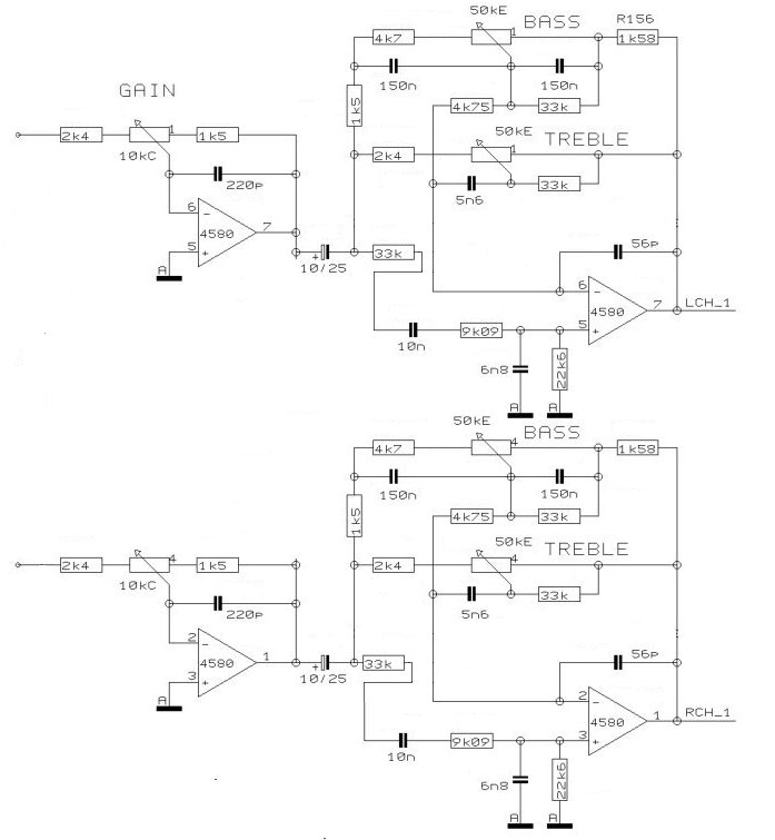
The modified channel preamp of VMX100.
Please note that in the above picture I’ve omitted all parts designators. This is is to make the schematic ‘universal’ that can serve as reference for modding either channel. All the values are marked on the VMX100 boards, so it’s very easy to identify which part is which. Also missing are the capacitors to smooth +/- VDC power rails and to remove any DC offset from main out.
The Electronics
At the implementation end of things, this project starts with the most fun part: Cutting the main board!
I’ve so far come to reason that a neat maximum length for a Eurorack PCB is about 110mm. As a Eurorack panel is 128.5mm tall, you’re then left with 18.5mm / 2 (= 9.25mm) free space for the panel to mount on the rack rails. Width is of course only limited by the maximum HP you want the module to have. So these are my recommended size guides to keep in mind when laying cut marks over the main board.

The VMX100 main board is about to get it!
On the above picture you can see where I chose to cut the main board (the black lines). These resulted in channel preamp boards measuring about 110mm * 25mm. So 5HP module is the smallest you’re going to using the board as-is, without any additional modding.

Channel preamp boards cut.
At least the main board is a double-layer PCB, so there’s absolutely no risk of damaging any inner layers, what you’d likely end up doing if cutting a 4-layer (or more) board. And really for Behringer it’s about keeping the costs down, so the less layers the cheaper once again :)
Input jacks were easy to add: Just use the holes where input toggle switches used to be!

Input jacks for both channels..

..and their wire connections on the solder side.
For mounting the output jacks, well, they really don’t have as good a spot as the input jacks do. At first I started drilling through-holes on the preamp board to match the jack solder pins, but came to my senses about how stupid it is shortly after. So instead I made this small daughter board, which piggy-backs over the preamp board with the help of pin soldered to ground planes. So:

Output jack solder pins trimmed.
The jack solder pins needed to be trimmed a bit, both to fit the veroboard and also to match the height of input jacks. As the input/output jacks will be later used to mount the panel over PCB the jacks need to be about level for this. Potentiometers are not of threaded type so for attaching the panle it’s either the jacks or standoffs, latter for which there really isn’t any room on PCB.

The daughter board, 100-mil (2.54mm) raster holes drilled to preamp board.
As a precaution I insulated the bottom of output daughter board with mylar tape, just to steer well-clear of any shorts.

Mounting pins of output board poke through mylar tape..

..and once board is installed, pins are bent against preamp board for soldering.
I also made a separate board for the Eurorack power connector, which connects to grounding pads of the channel input switch. Effectively covering the solder pads of input jacks.

Power connector board (blurry sorry!)..

..and its solder side…

..and the board installed!
One extra modification I added was to hook up the normalling pin on channel 2 input jack so that if nothing is plugged to it, the output of channel 1 is routed through channel 2. This will effectively double the gain, bass and treble boost (or cut) and possibly allow the opamp inputs to be overdriven (= distortion). I didn’t yet take any readings how this chained circuit performs, but based on what quick audio tests I did the bass / treble boost is definitely there.
Finally to wrap up the electronics side, I connected opamp (IC13) outputs to jack via 10µF capacitors and added 47µF capacitors between each power rail to ground. Both of these were values that seemed to be used for similar functions on the VMX100 main board, so that’s what it is for me too.

Electronics all good to go!
As a generic, marginally related veroboard tool tip / side-note: If you need to cut a trace on a veroboard there’s absolutely nothing better to it than a 3mm (or other similar-sized) metal drilling bit. Place the drill bit over the veroboard hole where you want to cut the trace and give it a few spins. Simple as that!

Veroboard trace cutting done the easy way!
The Panel
At first I was thinking of using one of the blank 6HP panels I have, but then instead decided to chop the VMX100 panel instead. Since I’m not modding the potentiometers then perhaps similar to electronics, a cutting hack is quite enough for the panel too.. and there’s no need to worry about panel markings!
Looking at the channel section on the panel, the gray dithering texture behind text ‘CHANNEL1’ is 30mm wide, so by cutting straight lines from its edges you end up with a panel slice 6HP wide. It’s a width that is perhaps a bit wide for a Eurorack module with this kind of feature set, but if opting to keep the panel texts intact (and off the panel edges) then there’s very little choice. The PCB is 5HP anyway, so I didn’t feel that trimming away 1HP is at all worth the hassle.
So yeah:

Where to cut the panel..

..and what it resulted with, jack through-holes included.
Using the VMX100 panel like I did (see above pic?), the most obvious downsides are that
- you’re left with a bit of channel slider hole at the bottom edge and
- input jack holes will have a gap in the middle, because these jacks land exactly to where the channel input switch was.
To quickly address these I figured I’ll just put some stickers on top and be done with it already! And so there it is:

ProtoTypo PT3a all good to go! :)
Not forgetting the most important part, aka the name of PT3a! Didn’t think of any other good abbreviation than Behringer Utility Module, so “BUM” it is (trololol).
For Later
Considering I shelled out 5 euros for the mixer and in return getting the spares I needed plus this Eurorack gain / EQ module, these already make it epic awesome bang for buck. But there’s more to source from what other bits remain!
First, since I still have the second channel preamp cut, I’ll be following up with PT3b build some time later. For this first model “A”, I just wanted to do a simple proof-of-concept hack and see how it works out. What I have in mind for model “B” right now, are at least to replace the stock stereo knobs with mono knobs so that each of the channels can be adjusted separately. Also output of first opamp could be sourced to a jack to output a inverted version of input signal. And maybe that mid-range EQ knob could be added too..
Second of course, there are the other circuit sections which are just begging to be hacked too. Maybe the tempo matching indicators would turn into a fun ‘blinky lights’ module, or whatever
So let’s see! Do subscribe to the RSS feed of this blog, or follow me on Twitter for more hacky build madness :)
Downloads
3 responses to “ProtoTypo PT3a – BUM”
Trackbacks / Pingbacks
- - 13/06/2017

Hi Mr. Elbowski,
I found you looking for clues to how to fix my Behringer vmx100.
Maybe you could help me.
What should be the rating of the power supply transformer?
It seems that mine is bad (open primary winding).
In all The schematics that I have found online this part is omitted.
VMX200 has +17v, +15v, -15v and +5v in various points (and I assume the vmx100 also), but voltage from the transformer is not stated.
Thanks a lot,
Michael
Hi Michael
The PSU in VMX100 is a standard electronics cookbook thing; first there’s the AC transformer with a double output secondary winding (sharing a common neutral) that outputs 9V-0V-9V AC @ 400mA, followed by a bridge rectifier (DC conversion) and 7805, 7812 and 7912 series linear regulators. So the VMX100 PSU outputs +5VDC for digital side (microcontroller etc.) and +/-12VDC for audio side (opamps etc.).
Based on this I’d say that the VMX200 is not exactly the same. However it most likely uses the same series of regulators, and this you could check: If it does, then judging by what you measured the you should find 7815 and 7915 regulators somewhere. The 7xxx series has a max. input voltage range of 35VDC (iirc) and the input needs to have at least a 3VDC overhead of what the regulator outputs (very iirc). So in your case it would translate to a input voltage range of 18 – 35VDC.
Seeing that the VMX100 PSU design works even if it omits the 3VDC overhead I guess, if you have one readily at hand, you could try a AC transformer with a dual output of 12VAC which would then translate to about 15VDC when bridge rectified.
I actually made a test power supply out of the metal box & PSU of my VMX100. I dug up a couple of pictures of that for you to use as reference:
VMX100 case with front panel and main board removed

VMX100 AC Transformer closeup (secondary output wires yellow-brown-yellow)

VMX100 7xxx series linear regulators (fastened to bottom to use it as heat sink)

So maybe check how closely your VMX200 matches these shots, and I hope this helps you getting things sorted. Good luck! :)